Which wire on 3plug ECU, or anywhere on the loom can I tap for the lambda signal????
Wiring an AFR meter to Lambda Circuit
-
#1
-
 Administrator
Joined: Dec 2002
Warrington
Posts: 20561
Blue Saxo VTS Turbo/White Megane F1 R26
#2It's easy enough if you tap into the lambda sensor wiring loom itself... I did know the pin, but not off the top of my head.
Administrator
Joined: Dec 2002
Warrington
Posts: 20561
Blue Saxo VTS Turbo/White Megane F1 R26
#2It's easy enough if you tap into the lambda sensor wiring loom itself... I did know the pin, but not off the top of my head.
I will check when I get home from work and post here...
Simo' -
#3Thanks M8. I thought I had found lambda wiring loom. blue Plug mounted ontop of gearbox. When I tapped the black wire, the meter did not read a thing. Power light was on though
-
Administrator
Joined: Dec 2002
Warrington
Posts: 20561
Blue Saxo VTS Turbo/White Megane F1 R26
#4Find the lambda sensor and trace it back towards the gerabox area... connector should be black with a red side clip which pulls out. There should be 4 wires...
The pin you need to connect to is either on pin 3 or pin 4... (checked in Haynes).
Not sure which is input and output from the diagram though... I will have a check on my car for you.
Simo' -
#5Thanks Dude, I have connected it to the black on the block, but get strange readings. E.G the lights on the meter are flying around everywhere and not rising progressively to a point like i would have expected. They just rise and fall very quickly. If you could have a look at where you have connected that would be muchos appreciated. Cheers.
Rich -
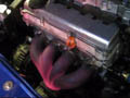
#6Are you conecting a Fuel/Air Mix indicator?? Like the one i have at the top of the three shown on the pic??
<img border="0" src= "http://ranjel.20megsfree.com/images/photo1055.jpg"> -
#7If so, you will be expecting it to move up (rich) and down (poor) like 3 times every second. This is the ECU working and trying to find always the best mixture of fuel and air. So if it moves up and down a lot its completely normal. Only when you push the gas pedal down for a second or two, will you se how rich or poor your mixture really is.
Hope this helps.
<img src= "smileys/smiley4.gif"><img src= "smileys/smiley4.gif">
-
#8Thanks M8, That helped. And thanks for all the vids you keep posting on SSC too, Most ammusing <img src= "smileys/laugh.gif">
-
#9No Problem Mate!!! Glad I could help..
Regarding the videos, I just sent Simo like 15 more!!!! We will have to wait for him to host them in the Video Section<img src= "smileys/smiley4.gif"><img src= "smileys/smiley4.gif"><img src= "smileys/smiley4.gif"><img src= "smileys/smiley4.gif"> -
Administrator
Joined: Dec 2002
Warrington
Posts: 20561
Blue Saxo VTS Turbo/White Megane F1 R26
#10The lambda signal should cycle up and down.. this is how the ecu targets its setpoint.... and alters richer/weaker accordingly.
Sounds like its wired in fine to me.. <img src= "smileys/wink.gif">
Ricardo... as soon as I get back mate.. <img src= "smileys/smiley2.gif"> -
#11<img src= "smileys/cool.gif">Cool!
-
 Saxperience Forum Bum
Joined: Jan 2003
Scotland
Posts: 3380
#12imformation!!
Saxperience Forum Bum
Joined: Jan 2003
Scotland
Posts: 3380
#12imformation!!
i have seen 3 damaged ecus, which have had A,.F.R meters attached to std sensor,do not guess at connections and keep the meter away from interference ,as the spikes can damage ecu. I only will reccommend stand alone units due to this -
Saxperience Forum Bum
Joined: Jan 2003
Scotland
Posts: 3380
#13std probe connectors have a sheilding in the wiring loom all the way to ecu ,there is a reason!!