Turbo dudes - Bracket / Support

  1. #1
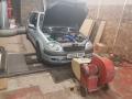
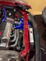
    For those who remain who are boosted (or know of any threads with pictures that are still active) how did you support the turbo's weight?

    I'm attempting to make a bracket. Looking for ideas.
  2. #2
    Turbo’s aren’t heavy they just bolt to the manifold and that hold the weight
  3. #3
    Quote:
    Originally Posted by AdamL200 View Post
    Turbo’s aren’t heavy they just bolt to the manifold and that hold the weight
    Maybe if yours is made of polystyrene.

    Unfortunately the weight hanging from the manifold and the contraction/expansion from the heat destroys them. Mine has already been welded once when a tiny GT17 was hanging on it. Long term you need it bracing.
    1 user thanked this post:
  4. #4
    Mine just hung off the manifold but I had a tubular manifold so don’t know if that makes any difference regarding strength etc
  5. #5
    I can't comment on the strength but the cituning one defo can't take the weight of this new turbo. It must be near 12kg I reckon or at least double the old one.

    You didn't have yours 2 minutes Craig!

    Something using rod ends is what I'm thinking, like so:

  6. #6
    Hahaha I know mate but I built it enjoyed it then moved on lmao yea good shout that
  7. #7
    I moved my battery and sat my turbo on the tray lol

    it's only pipes.
  8. #8
    12kg? How big is this turbo exactly lol
  9. #9
    I had no problems with a gt25 on a dp manifold, had a gt28 on there for a short amount of time also.
  10. #10
    Quote:
    Originally Posted by AdamL200 View Post
    12kg? How big is this turbo exactly lol
    It's big.
    It shouldn't be really, being inbetween at GT17 and GT25 in Garrett's range...

  11. #11
    Ye that is big lol but I still can’t belive it’s 12kg an actual garret t25 only weighs 6kg
  12. #12
    most oem stuff either have a properly hench cast iron manifold,AND a brace or two.
  13. #13
    Is it just the picture or does it sit that low down? You might run into issues with an oil return if it is sat as low as it looks
  14. #14
    looks to be above the top of the sump so should be fine.
  15. #15
    Yeah it does sit above so there is a downward slope for the return, a better pic is somewhere in my thread.

    For now, I've got a picture to work on how I might rig up the brackets. Possibly a bracket from the oil return flange, to a longer M10 bolt through the bell housing. Using tie rods to get the tension.... or I might ask the exhaust place to make a triangular bracket from the hot side flange...

  16. #16
    downpipe studs are good for this, link it up to the bellhousing bolt somehow if possible.
  17. #17
    Some of your cracking issues could be down the expansion and contraction differences since some of your runners are much longer than others.

    That and vibration are the usual culprits.

    A slip joint on runners 1 & 2 would probably solve it, obviously you need an inner and outer sleeve and they need to fit together properly (read "not shit tube with a nasty seam inside") or it will blow.
  18. #18
    I am using the cituning manifold also, my gt17 has a 8mm bolt hole underneath to which I had the exhaust place when adding a flexijoint into decat pipe make a little bracket out of some 6-10mm steel strips, it literally is basic as fck and bolts from turbo to gearbox, it won't hold a bus but is stopping any rocking/play and has been fine this far. As far is I no all turbos should be supported in some way.
  19. #19
    Quote:
    Originally Posted by sri_130 View Post
    It's big.
    It shouldn't be really, being inbetween at GT17 and GT25 in Garrett's range...

    How did you setup the return line from the head?
    And are you feeding the oil to the turbo from the front of the block?
  20. #20
    Quote:
    Originally Posted by Nimix View Post
    How did you setup the return line from the head?
    And are you feeding the oil to the turbo from the front of the block?
    Yes the feed is from the oil pressure switch on the front of the block.

    What return line on the head?
  21. #21
    Quote:
    Originally Posted by sri_130 View Post
    Yes the feed is from the oil pressure switch on the front of the block.

    What return line on the head?
    Nice and that provides enough pressure?
    Have you drilled a hole in the sump?

    The return line is the black tube you can see just above the thermostate

    It runs infront of the block giving less room to fit the turbo
  22. #22
    Quote:
    Originally Posted by Nimix View Post
    Nice and that provides enough pressure?
    Have you drilled a hole in the sump?

    The return line is the black tube you can see just above the thermostate

    It runs infront of the block giving less room to fit the turbo
    That's a breather. It's supposed to vent crankcase pressure to the head as to not impede oil return to the sump. On later adaptations of the engine it was removed. I'm going to remove mine, as it always pops out. I remember panicking that I didn't have the right pipes for it when I rebuilt the engine - until I saw a c2 vts which doesn't even have it from the factory!
  23. #23
    Sump has a tube welded in, for the return, yes.
  24. #24
    The top one is the breather, and only vents air in the intake.
    There's none on the other cover causes the oil cap to leak
    The JP4 got one in each cam cover (i've installed those on my car)


    But thank you for taking the time to answer
  25. #25
    Nevermind, you are correct - it's for the crank (just like you said)

    My mistake, the language barrier is not in my favor xD